Measurement Geometry Basics: Bidirectional
 The geometry of a measurement system defines the locations and optical characteristics of the light source, sample, detector, and the optics connecting them all. There are several standard geometries, all based on the document Colorimetry, 3rd Edition by the CIE (Commission Internationale de l’Eclairage or International Commission on Illumination). The CIE designation for the document is is 015:2004. |
Schematic of CIE bidirectional geometry designation 45:0a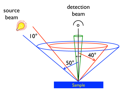 CIE 45:0a has a 10° wide cone of light incident on the sample at 45° to the sample normal. The “a” in 45:0a indicated annular meaning that the 10° cone continues uninterrupted all the way around the sample (all azimuth angles). This is shown by the blue and red cones. The detector is positioned normal to the sample, receiving light reflected from the sample in a 10° cone, shown in green. Alternative 45:0 configurations are 45:c and 45:0x. 45:0c indicates circumferential illumination, which is similar to annual except that it is distributed in discrete locations around the ring. For example, a fiber optic illuminator with 4 or more beams spread around the red and blue cones qualifies as 45:0c. 45:0x does not have ring illumination, instead uses a single beam at a single azimuth angle. The optical paths of each of these can be reversed and designated as 0:45a, 0:45c, and 0:45x. For most “well-behaved” materials the results from reversed geometries will be identical. Exceptions are materials that exhibit gonio-chromatic effects (those that reflect color differently in different directions). Special considerations are required for such materials. |